The client is a small independent that just made a $600 million bet on a new deepwater floating platform to develop a Gulf of Mexico field the majors considered too small to develop themselves. Get it right and the client doubles production next year. Get it wrong…well, do not go there. Mitigating installation risk with dimensional control makes a lot of sense when the stakes are so high. Here is how Bluewater Industries did it for ATP Oil and Gas Corp. (ATP) on the Titan MinDOC project earlier this year.
The moment of truth for all offshore installations: Will the topsides-to-hull integration be performed successfully, on the first attempt and without interferences? Bluewater Industries deployed dimensional control services from Intertek Hi-Cad at relevant stages of fabrication to limit the potential for installation problems, and cost and schedule impacts for ATP’s Minimum Deep Offshore (MinDOC 3) floating platform project. Installation and integration of the topsides modules was completed offshore in January without incident; no dimensional fitting or clash problems were encountered.
The ATP Titan project, a deepwater dry tree platform, is the first of its type to be used in the GoM. The patented MinDOC hull, designed by Bennett & Associates (BASS), consists of three circular columns connected by triangular pontoons and a top tensioned riser (TTR) frame that supports the risers through the center of the hull. On top of the hull sets a two module, “T-shaped” facility designed by Mustang Engineering. The structure measures approximately 726 ft (221 m) from the base to the top of its derrick and has a design capacity of 25 Mbbl/d of oil and 100 MMcf/d of gas. The Titan MinDOC has been deployed in the Mirage field (Mississippi Canyon block 941), as part of the Telemark Hub, and will be initially producing part of the Telemark (Atwater Valley block 63) and Morgus (Mississippi Canyon block 942) fields via subsea tiebacks in water depths of approximately 4,000 ft (1,219 m). The stakes are high – development of the Telemark Hub is expected to double ATP’s production this year.
At first glance, Titan’s three-column structure resembles a semisubmersible, but motion-wise, its deep draft and low center of gravity give it pitch, roll, and heave motions more in line with spar designs. This is particularly important for post-Katrina design conditions. The natural oscillation periods for the platform fall well outside the wave periods typically experienced in the GoM. Furthermore, the MinDOC was designed to be moved to new locations over its expected service life. The Titan can operate in depths ranging from 2,000 ft (610 m) to 7,500 ft (2,286 m) with comparable payload and environment conditions. Moreover, the unit can be towed to a new location with the topsides in place. As such, the Titan allows ATP to consider fields that would otherwise be commercially marginal with conventional completions.
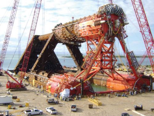
The 18,000-ton (16,329-metric ton), 485-ft (148-m) long hull was constructed horizontally by Gulf Marine Fabricators at the company’s purpose-built graving dock in Ingleside, Texas. During construction, two of the three 52-ft (16-m) diameter upper columns were supported by saddles located directly on the concrete floor of the graving dock, while the third column was assembled more than 100 ft (30 m) up in the air. After hull fabrication was completed, the 40-ft (12-m) deep graving dock was flooded and Titan was floated and towed to its deepwater installation site where it was upended to its operational position by controlled, free flooding of its lower hull.
The topsides consist of a 3,600-ton (3,266-metric ton) process module and a 2,500-ton (2,268-metric ton) utility module that were fabricated at Gulf Island Fabricators in Houma, Louisiana. In plan view, the topsides structure is T-shaped with the process module spanning 150 ft (46 m) across the port and starboard columns. The utility module spans from the forward column to the process module, where the two are connected via a structural interface. Weight constraints made it impractical to fabricate the topsides as one unit; the lift would have induced unacceptable deflections or required an impossibly large spreader bar or two crane barges to lift.
Intertek Hi-Cad delivered dimensional control for pre-installation structural interface compatibility and identification of potential interferences between the modules and hull.
Bluewater contracted Intertek Hi-Cad in April 2009 to provide dimensional control (DC) services for the Titan. In addition to general construction support for key components, Intertek Hi-Cad’s scope included detailed and high accuracy as-built dimensional data that assured compatibility between the topsides-to-hull and module-to-module structural interfaces. This compatibility analysis included clash-checking of the interface envelopes to identify possible hard clashes and close proximity components that could cause problems during module installation. As the project progressed, Bluewater elected to expand Intertek Hi-Cad’s scope to include assistance with the installation of the four 80-ton (73-metric ton) riser tensioners and pre-installation verification of the topsides-to-hull interconnect piping spools based on as-built module locations relative to the hull.
Discovering clashes and interferences during installation is a project team’s schedule- and budget-busting nightmare. With day rates for offshore installation operations often exceeding $1 million per day, there is every incentive to shorten the duration required for installation. Dimensional control is low-cost, high-value insurance to significantly reduce that duration. Although arrangements can vary, dimensional control contracts typically amount to less than 0.2% of total installed cost. “The cost of Intertek Hi-Cad’s services was insignificant in comparison to the negative schedule and cost impacts that could have been encountered during fabrication, installation, or operations. Their attention to detail and commitment to maintaining our project schedule have solidified their involvement in future projects of this magnitude,” says George Friedel, VP of Operations for Bluewater Industries.
Of course, safety always comes first. When lifting significant loads, whether at sea or on land, the priority is to safely and efficiently land the load. Leaving a load that weighs thousands of tons hanging on the crane, for any length of time, while resolving installation issues introduces serious additional risks, including the potential for a catastrophic accident.
In the case of offshore installations, success in installing modules (whose tendency is to flex in the lift condition) from a barge onto a floating hull structure demands understanding the potential dimensional issues that can be encountered during the approach, engagement, and touch-down of the modules to the hull.
“With mating tolerances as little as 0.5 in. or less on major structural components fabricated in separate locations in different states, you need the precision and accuracy of DC to make sure it all fits together. In most instances, you only get one shot to install modules the size of the Titan‘s,” says Jeff Rushing with Bluewater Industries. “Physical influences in an offshore environment make it impractical to have a second chance.”
This makes reversing the procedure (i.e., lifting the modules back up to field-correct for structural compatibility and interference issues) an impractical, and sometimes impossible, option.
Dimensional control workflow
Intertek Hi-Cad operations manager, Kyle McNeil, led the team that conducted the dimensional control work. Step one was to meet with Bluewater project personnel to understand the design tolerances, deflection, and movement issues specific to the Titan installation activities. McNeil is no stranger to offshore work – he’s been with Intertek Hi-Cad for three years and spent 26 years with KBR and McDermott before that. McNeil views dimensional control as an investment: “It’s down to the client and the investment in managing potential risk.”
Under McNeil’s supervision, Intertek Hi-Cad survey personnel visited the hull and topsides fabrication facilities at appropriate times to execute the survey work using a proprietary surveying processes and supporting software. The accuracy and detail of the survey work was critical to assess the structural interface compatibility and to detect and visualize possible clashes that could arise during installation. As each part of the as-built survey work was completed, Intertek Hi-Cad progressively calculated and fitted the pieces together to obtain a “best-fit” among all structures.
Construction support
At one stage of construction, the forward column of the Titan was supported elastically by strand jacks and trusses 100 plus ft (30 m) in the air after assembly and just prior to the installation of the TTR frame which would tie all three of the upper columns of the Titan together. BASS calculated the amount of deflection expected as the strand jacks were released and the structure was positioned in a location that would minimize locked in stresses on the hull. As part of this critical construction activity, Intertek Hi-Cad was asked to monitor the position of the TTR frame relative to the target positions provided by BASS to an accuracy of ±1/16-in. (1.586 mm) during the weldout. End Result? The stresses were minimized as predicted.
Topsides-to-hull structural interface
To properly mate with the module legs, stabbing guides on the hull were designed to allow adjustment in the x, y, and z direction before welding them to the hull. This adjustment allowance had to account for five factors: 1) the as-built geometry of the module legs, 2) the as-built geometry of the module-to-module structural interface, 3) the as-built geometry of the hull, 4) the welding tolerance of the hull, and 5) the geometry change anticipated as the hull moved from the horizontal, laterally supported condition to the upright and free-floating condition offshore. Intertek Hi-Cad surveyed the as-built locations of both the module legs and module-to-module structural interfaces to determine the “best fit” of the modules relative to the hull. With this information, BASS was able to pinpoint the optimum locations for the stabbing guides on the hull which significantly reduced installation risks offshore.
Once fitted and in place, Intertek Hi-Cad’s scope continued with monitoring the stabbing guides during weldout relative to target positions that were established. With Intertek Hi-Cad’s experience and twice-a-day readings, these optimum locations were accomplished despite the movement of the target positions due to expansion and contraction of the hull during the summer heat.
Offshore DC verification
Intertek Hi-Cad carried on with the DC services by measuring possible deflections that may have resulted from transportation and upending of the hull once it was floated to the upright service position and fully ballasted. The survey readings then were calculated and modeled in AutoCAD to determine the position of the structural interfaces, primarily the stabbing guides. Results from Intertek Hi-Cad’s work confirmed that the forward leg column had deflected out-board by close to the predicted offset and all elevations held to plane within ± 3/16 in.(4.75 mm).
Once the hull and topsides were mated, the next step was to connect the piping systems and install the specifically designed riser tensioner system. With Intertek Hi-Cad’s foresight to pre-survey the positions of the piping tie-in points on both the topsides and hull prior to installation, it was straightforward to carry out the minimal survey work necessary to calculate the geometry of the closing spools, which included lengths, flange angles, and bolt pattern orientation, where applicable. The required dimensional information for selected spools was completed and issued to piping personnel for fabrication completion – the goal: first-time fit.
Confined within the well bay structure of the utility module, the riser tensioners hung suspended in midair for the transportation offshore. Survey work had begun many months earlier in preparation of the installation. Intertek Hi-CAD had placed targets in strategic positions on the tensioners that would allow the proper alignment to be achieved as the tensioners were lowered to their final resting position on the TTR frame. This alignment was critical, as the tensioners were only able to be lowered into position prior to being put into service. Consideration of the utility module wellbay positions was included in the Intertek Hi-CAD best-fit calculations for locating the module to the hull. Once again, good survey preparation allowed for efficient and accurate positioning of the tensioners during the offshore installation.
DC technology
Total station survey instruments and accessories supported by DIMES (Intertek Hi-Cad’s 3D calculation software) and AutoCAD software were used as the main tools for the project survey work. The DIMES software is compatible with AutoCAD. Intertek Hi-Cad surveyors are experienced with 3D CAD modeling techniques, allowing the as-surveyed data to be manipulated in AutoCAD for the purpose of modeling relevant information and possible overlay against the design model for interrogation. In this instance, three separate models were prepared for the top of the hull and the undersides of the process and utility modules. Based on the calculations, the modules were moved into position on the hull model, thereby allowing interrogation of the full interface envelope. Working offshore with a total station instrument often requires flexibility and knowledge of the acceptable parameters to be able to set up the instrument in difficult situations and maintain high accuracy in order to achieve the required tolerances.
How is dimensional control different than inspection?
Here’s where experience with design, fabrication, and installation pays off. A dimensional control expert engaged throughout fabrication can not only identify potential fabrication dimensional problems and tolerance accumulations but can also advise on practical solutions to correct for the accumulations. Dimensional control insight into fabrication processes, experience and understanding of installation procedures as well as knowledge about the capabilities of individual contractors lets DC experts inform project teams about how to make mid-course corrections and adjustments to avoid potential serious expensive problems from occurring at the critical stages. McNeil says “it takes a client with an open mind to get full value for the investment because it is not business as usual.”
Other lessons learned
Construction of some offshore structures requires the coordination of multiple fabrication contractors, each responsible for producing components to a specified tolerance. The challenge for the project team is to manage the accumulation of the variations between the nominal design dimensions and the as-fabricated dimensions. Tightening the specifications has cost and schedule implications and in most cases becomes impractical. Due to cost and schedule concerns a project team can be pushed to take risk on out of tolerance dimensions. Dimensional control applied accurately and with construction experience and knowledge can provide the assurance that components will fit together when it really counts, the first time.
(This article was originally published in the May 2010 issue of Offshore and distributed at OTC.)
Contributors to this article include authors:
Robert Shivers, ATP Oil & Gas Corp.
Jose Vasquez, Roy Cottrell, Bennett & Associates LLC
Ian Mackie, Keith Medley, Intertek Hi-Cad