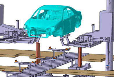
Two years ago Stephen Brennan, manager, production engineering, at Toyota Motor Manufacturing North America was in the company’s California design studio reviewing a clay model of the 2005 Avalon. One of the model variants has a lower-to-the-ground rocker panel, and the project team asked Brennan a sequence of questions all centered on what changes to the production line would be required to manufacture the new model. The issues were clear. What tooling would have to be modified? What new equipment would have to be ordered? Half of the problem was very well defined – Toyota has some of the world’s most sophisticated 3D CAD design tools and the geometry of the new Avalon was well defined. Missing was detailed 3D information about the production equipment such as the slat conveyors, sublifters and lifters – the equipment that moves the car body and its components down the line for assembly operations.
Brennan’s epiphany came when he realized if his team had high-fidelity (±3mm) 3D CAD geometry and the ability to add kinematics to the existing production equipment, then the questions about what equipment would need to change, what this would cost, and how long this would take could be answered with confidence. The challenge was that much of this equipment, even in comparatively new facilities such as Toyota’s, was designed in 2D in the first place. Production equipment is typically not modeled in 3D. Little if any design information about the equipment was available in CATIA V5, the software Toyota uses for design. Moreover, the equipment has a lifecycle of 15-20 years and often the equipment is field-modified. Such modifications are rarely documented in 3D CAD models.
Laser scanning used to capture production equipment geometry
Here’s where laser scanning comes in. After proving the concept by building CATIA models of select production equipment based on manual measurements, Brennan had in-house contractor Mark Holtz, digital engineering specialist, investigate using 3D laser scanning to capture accurate and complete digital information about production equipment geometry. After several failed pilots with scanning equipment ill suited to capturing information about machines that are as big as 10m x 8m x 8m, Brennan’s team has found success using a work process developed jointly with Can-Tech Design, Guelph, Ontario. Holtz and Can- Tech have executed 15 scanning projects using a Z+F Imager 5003 scanner, and have produced CAD geometry for approximately 250 production machines at 3 Toyota facilities in North America.
Capital investment avoidance is biggest benefit
Brennan reports that Toyota saved several million dollars on one project alone, and that the payback is 10 to 20 times the scanning investment. How? Brennan says the biggest benefit of using 3D laser scanning to capture equipment data comes from capital investment avoidance. Often existing production equipment can be re-purposed to accommodate product design changes, saving unnecessary – i.e., wasteful – capital investment. These savings go straight to Toyota’s bottom line.
Project funding for the laser scanning and follow-on modeling came from project budgets, not strategic overhead funds, and had to be justified by each plant. Brennan says he had to make the business case to three Toyota presidents – the essence of the case was capital avoidance, and this value is what overcame the primary objection “why should we pay you to model equipment we already have?”
How is capital spending avoided? Not only can the contingency reserves for scope changes be reduced, but Brennan says the company no longer has to rely on its equipment vendors for equipment design modifications – “we know what needs to be changed and can develop tighter estimates for the real costs.”
Having accurate 3D data based on laser scanning about assembly equipment also means that production – the heartbeat of the company – can have a greater role in influencing product design. Brennan explains that often changes can be made to product design that are transparent to the end-consumer but can have a material impact on manufacturing cost. To achieve this, timely and accurate 3D information is essential. Also, with accurate 3D data “you don’t have to be an engineering genius” to solve these problems, says Brennan.
Often the as-installed equipment is different than the as-designed – Holtz says that “in the CAD world everything is perfect, whereas in the plants there are pieces of equipment that have been modified and are slightly different than the few original 3D models that we have.” 3D laser scanning is a new tool to enable production managers to manage variances between design and plant floor conditions.
Work process: laser scanning to CATIA
Can-Tech’s work process is to capture the point cloud data with a Z+F Imager 5003 scanner, then register and model the point cloud data in Z+F LFM software. Scanning is performed on weekends to avoid interrupting vehicle production – Toyota plants operate 2 shifts per day, 5 days per week. According to Can-Tech president Les Orford, a 2- or 3-person survey team can capture as many as 15 machines in a weekend of scanning.
LFM solid (SAT format) models are created, then exported as STEP geometry (STEP is the universal translation file of solid model data between different CAD systems) for subsequent importing to CATIA by Toyota engineers. According to Orford, model accuracy is ±3mm.
The modeling effort is significant as it can take 15-40 hours to model each machine, depending on machine complexity. Toyota next creates sub-assemblies of the data, then uses the CATIA models for DELMIA to create simulations of machine kinematics. Consequently, very detailed information about pivot points, motion sequence and the full range and extent of motion has to be captured. Brennan says Toyota has been working with DELMIA to address shortcomings in the motion simulation capabilities of the product uncovered by the process.
Going forward
Data acquisition would be improved by having lighter, less power-hungry scanners with wireless control, according to Holtz. Having integrated color and laser scan data would also be an advantage for interpretation and processing of point cloud data. The modeling step of the work process requires practitioners who not only understand the equipment being modeled but also have an appreciation for the strengths and limitations of point cloud data as well as high-end 3D CAD modeling experience.
Holtz also says that the work process could be streamlined if large point cloud data sets could be displayed and manipulated directly in CATIA. Currently CATIA can handle only highly decimated data, according to Holtz. [The capability to display, navigate and manipulate point cloud databases of hundreds of millions of points directly in other sophisticated 3D CAD environments such as Intergraph’s PDS and Bentley’s MicroStation already exists – we believe that this capability will come in time in applications such as CATIA, UGS NX and Pro/ENGINEER – Editor.]
Conclusion
No one in the automotive industry expects reductions in product design changes any time soon. Vehicles are getting bigger and product variation is ever-increasing. Product design changes stress manufacturing systems – will the new design pass through the existing paint shop? Will the carrier still fit the car body? Where are the new contact points? What equipment needs to be changed and when? 3D laser scanning brings a new way to tackle these difficult problems, cost-effectively.
About Can-Tech Design
Headquartered in Guelph, Ontario with an office in Erlanger, Kentucky, Can-Tech Design Inc. was founded in 1995. According to founder and owner Les Orford, the company has executed 15 scanning projects using a Z+F Imager 5003 and a Leica total station. Can-Tech has a technical team dedicated to creating 3D geometry including CAD models from scan data.


