Q&A with U of Arizona grad student Gabriel Birch
TUCSON, Arizona – Interest in photogrammetry has increased recently as software advances have allowed for detailed, and accurate, point clouds to be created from thousands of images. But we all know you need multiple photographs taken of the same object from slightly different angles to start extracting 3D data, right?
Well, that’s what Gabriel Birch and his fellow researchers here at the University of Arizona are out to change. In Vol. 20, No. 6 of Optics Express, Birch, Scott Tyo, and Jim Schwiegerling published a paper, “Depth Measurements through Controlled Aberrations of Projected Patterns,” which detailed their work in creating “a method of extracting depth information with a single camera and aberrated projected pattern.”
Essentially, they’re creating 3D images from 2D images. To find out how, and why, they’ve gone about doing this, SPAR 3D conducted an email interview with Birch, the results of which, with some slight editing for easier reading, are below:
SPAR: What’s your background in this and how did you come to start researching 3D image acquisition?
BIRCH: I am a 4th year PhD candidate in Optical Sciences here at the University of Arizona. I received both my BS and MS from the College of Optical Sciences, and should be completing my PhD sometime in the summer. I’ve worked on a lot of different projects over the last couple of years, with emphasis on imaging systems and medical devices (especially endoscopes). Dr. Tyo, my research professor, and our close collaborator Dr. Jim Schwiegerling jointly started working on this 3D device around one and a half years ago, and I jumped at the chance to help. I’ve had the opportunity to see this new modality go from just a concept on paper to a full-scale lab setup that I built. It has been a fantastic opportunity!
SPAR: When you say 3D images, I’m assuming you mean real 3D and not stereo 3D? As in something that can be rotated and you can see the back of? What form does the 3D image take? A point cloud? A mesh model? Can that image be exported from the software you’re working with and opened in other 3D modeling programs? How would viewers look at their 3D images? Can the image be manipulated?
BIRCH: This device can only measure what is in its line of sight, so we don’t capture a full 3D model with one set of images. Rather, we capture the depth information of the scene in relation to the camera. I suppose that we could take a few sets of pictures at different spatial locations and start stitching our depth data together to create a 3D model, but I haven’t done anything like that yet.
I should probably back up for a second and quickly explain how the camera works. As I’m sure you know, stereoscopic imaging is probably the most common method of 3D imaging. When we first started this project we wanted to move away from traditional depth measuring devices and attempt something a little unique. Our device does not determine depth through stereoscopic (ie., triangulation) means, but instead uses what we call a “depth modulated pattern.”
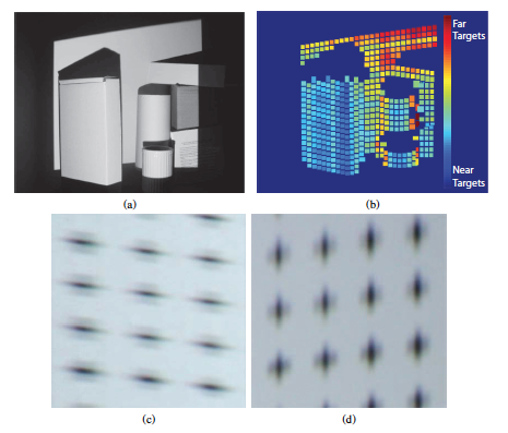
We essentially project a pattern onto a scene, but this pattern is modulated in a very particular way. By imaging the scene with this pattern incident on it we can determine the distance of objects in the scene from the camera. The big value added with this method is that it gathers 3D data with a single lens camera and, maybe even more importantly, this method does not need camera/projector angle differences like structured light methods require. In fact, this method works best if the camera and projector optical axes are coincident!
This scenario would enable 3D imaging with no shadowing caused by the 3D nature of the object obscuring the projected pattern. What this means for the imaging is that we can only gather depth data for objects that we can actually get the projected pattern incident on.
The big difference with this 3D measuring modality is that we get depth information without relying on triangulation or something like time of flight. That is probably our biggest contribution, and I’ll talk in a bit about some possible applications.
SPAR: Can that image be exported from the software you’re working with and opened in other 3D modeling programs?
BIRCH: As far as exporting 3D data into a modeling program – we haven’t done that yet but it is entirely within the realm of reasonability. There is so much to do and not enough time in the day!
SPAR: Is it possible to take measurements from the image you’ve created?
BIRCH: Yes. This is a quantitative depth-measuring device. I can actually produce estimated depth from the camera in millimeters.
SPAR: How would viewers look at their 3D images?
BIRCH: This is a great question, and something I thought about a lot. Firstly, it is important to remember that this device is really a scientific camera – it gathers quantitative depth information about a scene and constructs a depth map. You can display the depth map in a series of ways: point clouds, a mesh, or an image that colors in isoplanatic regions of depth to a particular colormap.
The key is that depth map contains the information about your camera-to-object distances. Once you have the depth map it is possible in post-processing to artificially select depth of focus and a whole host of other things. For applications in machine vision a depth map is probably all you need. For applications where we deliver a 3D image to a human being for a decision, a raw depth map is probably not the best way to go.
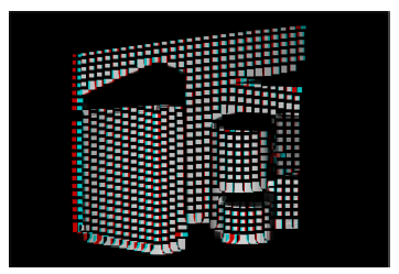
Late last summer I had a bunch of science teachers come into the lab and I was trying to explain how the depth map really delivers the 3D information, but they didn’t quite buy that this was a 3D camera. Specifically, I was trying to decide how to display non-stereoscopic-based depth data, so I decided to start working the stereoscopic math backwards. When you have a scene image and a measured depth map it is entirely possible to start dividing the image into isoplanatic depth regions, and create simulated pairs of stereoscopic right and left images, which could then be displayed on a polarized 3D screen or the older red-cyan anaglyph method. This is one of the major ways we plan to deliver 3D images to humans.
SPAR: How is what you are doing similar/not similar to software (like, say 123dCatch) that takes multiple images and combines them to create a 3D image?
BIRCH: I am not super familiar with 123dCatch, but it appears as if this is a great software tool that does a whole bunch of intense image processing to recreate a 3D mesh. It looks very interesting, but I suspect there is some heavy duty computations going on behind the scene. If they use automated feature detection algorithms to find common points in images, this method would have a lot of trouble if there was a low contrast object that was being measured, or if the object had a lot of repeating patterns in it. Also, I believe they stated you need tens of pictures to get a good 3D mesh, so time to take a set of images is probably going to be an issue for certain applications. This is a really cool software though!
SPAR: What would be the advantages of your way vs. they way described above?
BIRCH: We think of our application as a new modality in the 3D imaging systems toolbox. All tools excel and fail in certain areas. A great area of success with this modality is the ability to be scaled down. Since depth is not gathered via multiple pictures at different physical locations, and depth is not gathered via stereoscopic methods that require separation between the two cameras, we really have the ability to make this system very small.
The image processing is pretty tame and doesn’t require any sort of correspondence solving like quantitative 3D measurements using stereoscopic methods require. Because of this, we will be able to optimize our code and push the 3D measurement software to operate in real time.
SPAR: Are there applications you envision for your research?
BIRCH: We looked at this modality’s value proposition (able to scale down, quantitative measurements, no modifications necessary to imaging device, and can work up to real time display of 3D images), and tried to find applications that needed these qualities. We think that application is endoscopy. Currently 3D endoscopes suffer because the majority of them attempt to gather 3D data via stereoscopic measurements. This modality constantly pushes the optical engineer to try to expand the camera separation to increase depth resolution. However, endoscope size is generally a highly constrained parameter, so stereoscopic endoscopes are always trying to balance high spatial resolution, high depth resolution, and small endoscope size. This is really hard to do!
Our device bypasses this problem because the illumination channel and imaging channel can be located spatially very close to one another (even coincident if possible). The challenge we’ll have is to design the modified illumination channel, but this is achievable and there is work in the literature that has shown illumination similar to what we propose.
We’ve talked to some experts in our medical imaging community, including the actual endoscope-using surgeons, just to make sure we are truly seeing a problem that needs solving. Their response has been really positive, so we are moving forward with some of that work. We will probably focus on very challenging surgeries first, such as neurosurgery or fetal surgery – situations that require extreme precision from the surgeon. Gathering the 3D image and displaying this information in a user friendly way (like reconstructed stereo image pairs) could provide some significant advantages to these types of surgeries.