3D laser scanning improves the efficiency and safety of operations of nuclear power plants during scheduled outages. A growing number of case studies attest to industry support for the technology as operators and contractors discover more ways to utilize it.
Speed, Accuracy and Integration Aid Operations
Plant operators report that the speed of laser scanning allows them to attain the needed measurements inside containment structures and other areas within tight shutdown or “outage” schedules—oftentimes up to 10% less time than traditional methods. At $1 million a day for operation, this shortening of schedules is greatly welcomed by plant owners. This schedule savings also contributes to less time in the field for workers, thereby limiting their exposure to hot, high-dose site conditions. Additionally, operators can conduct their operations remotely amid many other activities taking place at the same time as well as capture data of hard-to-reach, dangerous areas.
Common control, such as fixed control points established with precise optical surveying methods, makes laser scanning even faster. By placing targets on known points, operators can reduce processing time and produce tightly registered point clouds tied to a plant’s coordinate system. Some plants are georeferenced in addition to having their own local coordinate systems.
With laser scanning, operators in nuclear facilities report capturing accuracy rates of 2-6 mm of the complex environments which include an array of equipment, piping and structural components. Further, today’s scanners are not impeded by their thermally hot—40°C (104°F) or higher—conditions.
More and more, a wide variety of downstream users, including health physics managers, investment officers and fabricators–in addition to designers, engineers and contractors–are benefiting from augmenting information such as imagery and CAD with laser scans. For example, adding geospatial data to Automated Mapping/Facilities Management (AM/FM) information associated with GIS databases improves the quality and efficiency of operations, and aids operators in maintenance and upgrade planning by digitally providing the actual location of a component together with its age, service record, manufacturer, model and more. Better data yields better designs.
And while 3D laser scanning may not cost less than traditional data collection methods in every case, many nuclear plant applications do reveal scanning to be less expensive. Cost savings of between 5 and 7 % are attributed to fewer and shorter site visits as well as the resultant high-quality data used for verification and inspection.
Combining Scanning and Photography
At SPAR 2009, Dr. Burkhard Wassmann, a consultant for technical documentation at the Biblis Nuclear Power Station in Germany, explained that he has been developing a documentation system that provides geospatial data for even the hottest rooms inside containment structures. His approach both limits radiation exposure for operations, documentation and maintenance teams (the safety benefit), and provides high-quality technical information on the facilities to improve the 3D workflow (aiding in cost savings). The geospatial data is used in planning maintenance and upgrade activities at the plant, including 3D modeling and clash detection.
After establishing precise instrument points and targets in the containment areas with total stations and optical levels to accuracies of 1-2 mm, Waasmann said the scans are easy to register and that photographs can be attached to the correct location and orientation.
The 3D laser scans from his team’s phase-shift scanners are then combined with spherical panoramic photographs to create photorealistic views of point clouds. Wassmann said he is pleased with the speed and precision of the phase-shift instruments as well as their ability to measure the variety of surface colors and textures in the plant. He explained that a professional photo team captured more than 72 photos at each scanning station using multiple dynamic range settings to obtain optimal images. Then, an automated stitching process produced the panoramic images with an accuracy of 3 pixels. To save time, the scanning and photography teams worked independently.
The Biblis plant also utilizes what’s called the bVision data administration and visualization tool. This tool allows users to see point cloud and photo images from the same viewpoint. The result is improved visualization and exceptional detail and accuracy. Users can identify points of interest in photo images and immediately receive digital information from the underlying point cloud. Other plant databases can be linked to the spatial data that include dosage information and CAD models.
High-efficiency As-built Analysis for NRC Generic Letter 2008-01
A recent regulation followed by nuclear facilities is the U.S. Nuclear Regulatory Commission Generic Letter 2008-01. The letter requires inspection and analysis of plant piping systems to confirm that construction and as-built drawings adequately reflect the true as-built plant construction. Contractors work to seek out high-point locations with potential bubbles of gas accumulation that can get hot and cause leaks. One method to obtain the analytic information is by scanning.
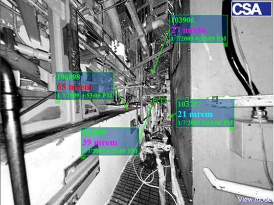
Augustine Cardillo, with Westinghouse Electric Company, and Amadeus Burger, ofCSA Inc., explained at SPAR 2009 that they are utilizing phase-shift 3D laser scanners to capture high-accuracy detail on piping at several nuclear power stations in the United States, including Arizona, Georgia, Pennsylvania and Alabama. They use the information to comply with the Generic Letter and to spot unvented high points or other areas where the actual piping differs from the original design information.
The measurement process requires extensive preparation, including scheduling and work activities, especially when working inside containment areas. However, Cardillo says, this approach is still a time savings, as operators who use other methods usually must set up scaffolding or use lifts to gain access to many of the pipes to obtain the needed precision; scanning eliminates this extra cost and time requirement. It also ensures that no measurements are overlooked, he says—a few hours of scanning can obtain more and better data than several days of manual measurements.
The resulting point clouds are combined with existing CAD models of the piping design. Optira President Mitch Schefcik described a second technique in which a virtual section of pipe ‘slides’ along the point cloud to expose local high points or deformation on the order of 2 mm. One snag, note Burger and Cardillo, is related to insulation on the piping. While scanning with the insulation in place greatly reduces the time and cost of the surveys, it can also introduce uncertainty into the analysis. They are working on ways to address the issue.
But while those who espouse scanning as the preferred method to address the Generic Letter, claiming that traditional measurement techniques that involve manual taping, optical or fluid levels, and hand notes and sketches are not only slow and costly but often overlook key measurements, others see more conventional methods—specifically total stations—as the best approach.
AREVA NP’s Metrology team has successfully supported five different plants using total stations to perform high-point piping inspections. “With this process,” says Product Manager Paul Nicholas, “we have afforded our customers the ability to make informed decisions on where to perform their next NDE (nondestructive evaluation) inspections on plant piping safety systems prior to demobilizing from the site.
“The total station is more efficient in both time and data collection. Points are collected only on the surface of the piping systems in question, which eliminates noise in the data and the requirement of having to register the scan locations together before evaluating the data. All data collection is performed real-time and the customer knows the results before breaking down the equipment.”
Further, Nicholas says, total stations provide accuracies of 0.030”. “Customer isometric drawings are updated onsite to reveal high point areas in the piping systems. They also support future decision-making processes as well as potential regulatory reviews,” Nicholas says, adding that the data collected is in a true gravity system versus a best-fit system that has to be established when utilizing the laser scanner.
“I love scanning when it is utilized correctly,” Nicholas concludes. “I do not believe that it is the most efficient method for identifying high point vent problems in plant safety systems.”
Advanced Data Management from EDF
How do you manage the immense amount of geospatial data from 58 nuclear power stations? Ask Raphael Marc from Electricité de France (EDF). Marc explained at SPAR 2009 that EDF has used 3D laser scanning for years and has developed an extensive library of data. Now, the company is bringing online its new SAAM (Software Architecture Analysis Method) software framework to combine the geospatial data with imagery, CAD and asset management. SAAM users can access point clouds or 3D data from within CAD views and can also see 3D CAD objects in the point clouds. The SAAM asset management module manages the geometric information, metadata and traditional asset information to give planners direct access to detailed information on plant fixtures and components. This also aids Marc’s goal of shortening maintenance planning and execution and other activities that take place during scheduled plant shutdowns. EDF uses 3D virtual reality simulations in its planning, which requires easy access to information on the location, dimensions and condition of all components inside a plant’s containment structure.
Using the SAAM Colisage and Planche modules, planners can examine available space for items that are moved or replaced, including clash detection, floor loading, ‘forbidden flyover’ zones and suitable work clearances. They can conduct multiple simulations of the planned activities and select the best scenario. The system reduces risk during maintenance operations and documents the work that occurred during the outages.
4D information is also being implemented for the work. EDF is heavily standardized and shares unified designs and procedures across its plants in France. Workers can compare information from different plants and verify work results by comparing scans taken at different times. Additionally, the SAAM system helps document the capability of the outage planning and execution to safety regulation authorities.
As part of its ongoing maintenance work, EDF scanning teams are constantly busy, Marc said. They are able to measure approximately one reactor building each week, collecting more than 50 million points. Marc said it takes about two months to process the data from a week’s worth of scanning.
John Stenmark is a writer and consultant working in the geospatial and AEC industries. A licensed surveyor, he has more than 20 years’ experience in technical support and product management with Leica Geosystems and Trimble Navigation. He moderated the nuclear facilities track at SPAR 2009. Lieca N. Hohner is Spar Point’s chief editor.