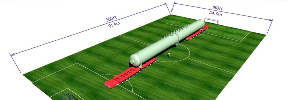
The desalter model measured against a soccer field
You might have moved a big piece of equipment fabricated offsite to its final position, but it probably wasn’t anything like this. Vic’s Crane and Heavy Haul was tasked with moving the largest desalter in North America from a manufacturer in Houston, Texas, to a refinery in St. Paul, Minnesota. The desalter weighed 281 tons and stretched over 50 meters—that’s 70% of of the length of a standard soccer field.
How did they move it across the country? How did they get it onto barges, through tunnels, across roadways, and through a facility not designed to accommodate an object of this size? How did they do it without a single clash, on time, and on budget? With 3D tech.
Background
Vic’s Crane and Heavy Haul, based in Rosemount Minnesota and founded in 1952, specializes in crane services as well as heavy haul and heavy lift solutions.
As the company grew, they found that they needed 3D software to view the models for the large industrial projects they were working on. This allowed them to add their cranes and equipment to the 3D models to perform tasks like clash detection. They’ve been using Bentley products for years.
With this desalter job, project manager Paul Newman explained, Vic’s was ready to take the step into 3D imaging. “A laser scanner has been on Vic’s wish list for years. However, the investment in the technology is sometimes difficult to sell to management. We felt that the accuracy and quality that this project would require would give us the perfect business case we needed to finally add a scanner to our engineering toolbox.”
Management OK’ed the proposal with the expectation of ROI in five years. They saw it much, much sooner. Here are three huge problems their scanner solved right out of the box.
Problem 1: The Mississippi River at a Record High
For the first part of the 2000-mile trip, one of Vic’s competitors loaded Vic’s transport equipment and the desalter onto a barge that would bring its cargo about 2200 miles down the Mississippi river to a dock near St. Paul.

The problems started right at the unloading stage. “The barge was originally scheduled to arrive in Minnesota in early June,” Newman said, “however, a very wet Spring brought the Mississipi to the seventh highest level ever recorded. The receiving dock was flooded through the end of June. If we tried to unload the
desalter directly to the dock area, there was a good chance our transporters would sink right up to their axles.”
Vic’s laser scanned the dock area to get precise as-built and as-is measurements, and then loaded that scan into Bentley’s AECOsim building designer. With the 3D information as a baseline, they were able to drop in the standard ramp components they had already modeled and design a ramp to support the transportation vehicles and the desalter.
It worked, but that was just the start of Vic’s challenges.
Problem 2: A Bridge (and Road) too Small
With the desalter on land, all Vic’s had to do was drive it to their client’s refinery. Considering that the whole rig, including transportation equipment, was 70 meters long, 5 meters tall, and 420 tons, that task was easier said than done.
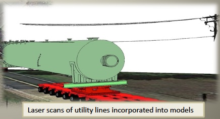
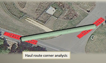
To prepare for moving the oversized load, Newman explained that Vic’s analyzed the entire transport route. They performed a clash detection for every corner the load would negotiate. Next, they identified every above-grade utility it would pass and laser-scanned it for inclusion in the clash detection analysis. Lastly, they identified utilities that were at or below grade, and determined allowable ground-bearing pressure.
Vic’s compiled all of this into AECOsim building designer, which allowed them to generate deliverables for utility companies, railroads, and highway departments to review. They applied to the Minnesota DOT, received a permit for their project, and under the cover of night moved the desalter to their client’s parking area.
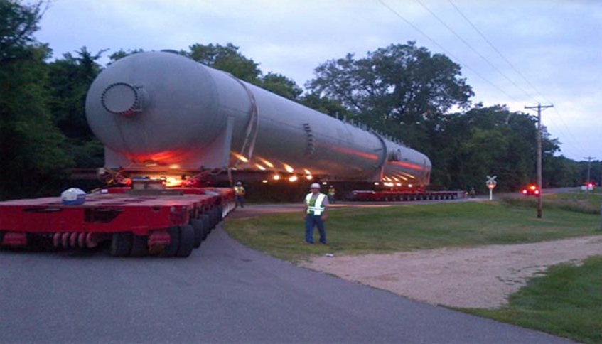
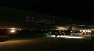
Moving the desalter
But the client’s facility included a pipe bridge that couldn’t even support the axles of the transport equipment. The solution, of course, was to build another bridge on top of it. As they had done with the dock, Vic’s scanned the existing bridge to get an as-built, brought it into AECOsim, and designed their new bridge. They even used the software to perform a clearance check for the transporter’s axles. Problem solved.
Problem 3: Pipe Rack Clash
As always, there was one more obstruction for Vic’s to negotiate before laying the desalter on its foundation in the client’s facility: a pipe rack.
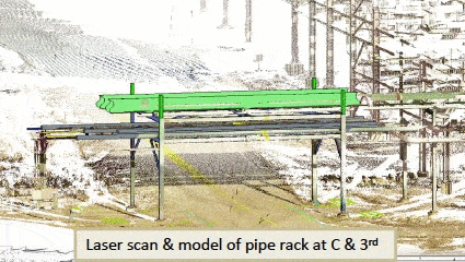 “The rack could not be raised due to critical system piping,” Newman explained, “and we were limited to how deep we could dig underneath the rack by existing underground utilities.” What’s worse is that the road starts sloping uphill immediately after the pipe rack, which pushed the load up toward the bottom of the pipe rack.
Vic’s solved the problem by creating a low-density scan of the road and pipe rack, and then using terrain modeling and road-design features in Bentley’s GeoPak software. They designed a a new road and gave the model to their earthwork contractor in a format that they could feed directly into their survey equipment. Using those deliverables, the contractor was able to lay out and construct the new road easily. No more clash.
3D for Communication
To show the client how their solution would work, Vic’s cooked up a short animation that included the new road design, the laser scans, and the model of the loaded transporter. Everything fit, as expected, but the animation also showed them that the existing road grade at the top of the hill would cause another clash. It would have shut down their operation, but since they caught it in time, it was an easy fix.
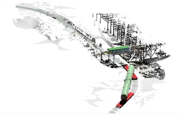
A still from the rack clearance study animation
Success
All this scanning and modeling worked beautifully. “The installation went exactly as planned,” Newman told me. “After a total transport and installation time of less than 10 hours, the new desalter vessel was now secure on its permanent foundation, right on schedule.”
In addition to a strong new relationship with the dock owner and a happy client, Vic’s had developed a holistic new workflow process using 3D technology and incorporating 3D scans into “every aspect” of their work.
“Using the scanner for the desalter project was so successful,” Newman says, “that we now incorporate it into nearly every project we design. As a result we expect a complete return on our investment in less than 30 months. Additionally, the use of laser scans by Vic’s crane division has cut the time it takes to create even simple critical lift plans in half.”