
DataSight was founded by experienced surveying, engineering, hydrologic, geologic, and geospatial professionals with extensive experience in these fields. Today, its customer base is primarily in the AEC industry wherever topographic modeling is required. DataSights’ largest clients have geospatial divisions within their organizations that utilize the company’s services to streamline their in-house mapping services.
DataSight is the developer of Breakline Builder, a SaaS product that originated as an in-house response for a better solution to breakline creation. DataSight’s Breakline Builder allows users to better leverage lidar data, that can then be used to produce a model of the object scanned. Objects as small as a penny and as large as many thousands of acres are scanned using lidar, resulting in an enormous amount of data produced quickly. Breakline Builder analyzes the point cloud to accurately identify shapes within the terrain and converts those shapes into much smaller and more useable data.
Contours versus Breaklines
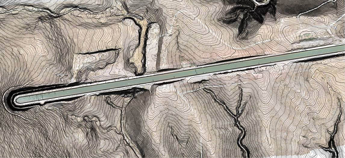
The term “breakline” is often used in combination with “contours”, but they mean different things. Both contours and breaklines are representations of the shape of a piece of ground. A contour represents a slice of the terrain at a specific elevation. Contours allows the viewer to see changes in elevation at a glance, but provide only a rough digital model of the surface. Breaklines, when done correctly, provide specific detail beyond the contours, adding facets to the terrain model. Contours can be very accurately created from breaklines, but not vice versa.
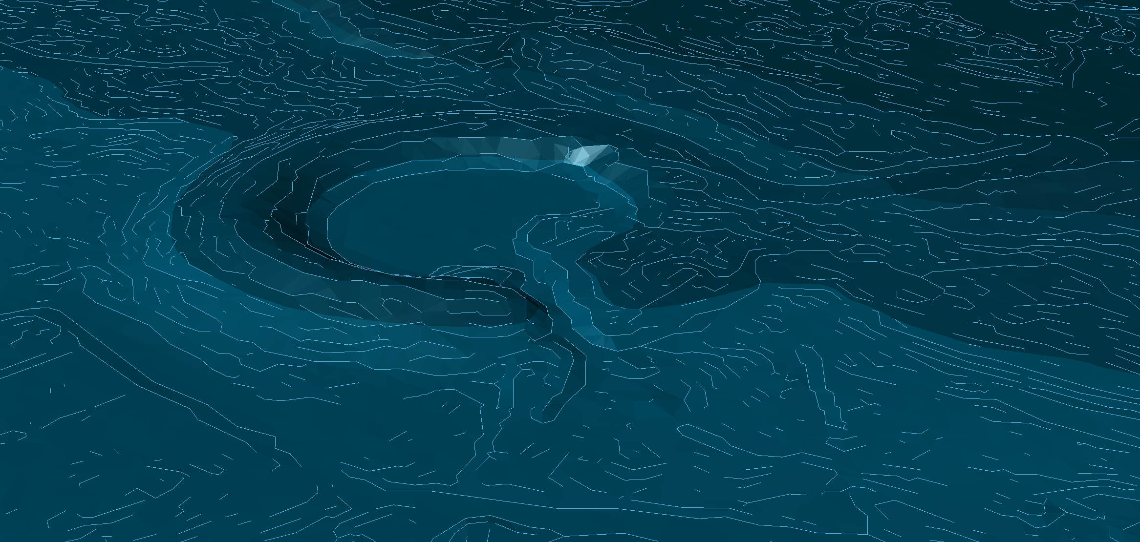
Breaklines exist everywhere there is a crease in the grade. When the slope of a spot on the ground differs from the slope of an adjacent spot, that is a break in the grade and defines a ridge or crease in the surface. Those creases and ridges are where breaklines are created. And most often, they are not visible to the human eye unless seen from just the right angle with just the right lighting. Breakline Builder finds breaklines that would be missed otherwise.
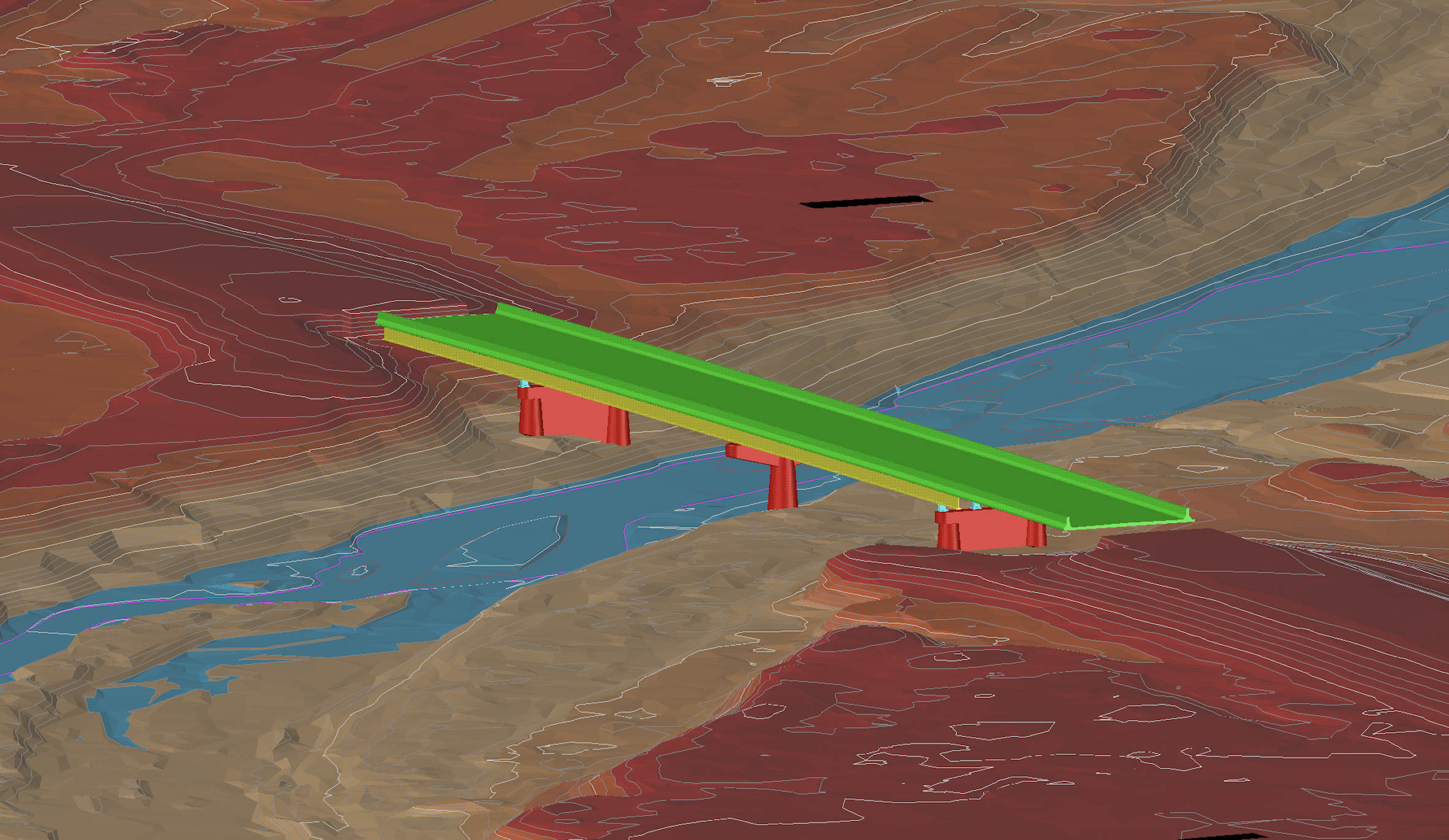
The breaklines created with Breakline Builder are perfectly suited to DTM building. In the traditional definition, a DTM is a terrain model composed of many different types of digital surveyed data, including breaklines, points, contours, and boundaries. Autodesk has included newer complex object types such as grading objects, COGO points, recap files, DEM’s, and feature lines. Datasight creates the DTM basics: breaklines and points. This makes it completely compatible with any DTM creation program, whether it’s from Autodesk, Bentley, Esri, or any other terrain modeler. DTM’s that are made solely from breaklines and points are an accurate and efficient way to define detailed terrain models with the smallest possible dataset.
DTM Building Process
To create a DTM from a point cloud, it is typical to classify the data to ground and non-ground layers of points. Breakline Builder requires a ground classified LAS or LAZ. Once the points are classified, a user could move on to manual digitizing if they had to, or they could send it to DataSight’s cloud-based software. They also need to create a closed polygon that defines the area of interest (AOI) within the point cloud that they wish to have processed. This can be either a shape file (SHP) or a drawing interchange file (DXF).
Once the classified LAZ and the AOI are ready, they are uploaded through DataSight’s website to secure storage at AWS. The DataSight system begins by creating a preview of the point cloud showing the AOI overlayed on it. This is a reality check for the user to make sure they have uploaded the correct data and that they are in matching locations. Once they see the preview, they can either cancel or run the project.
From there, the project is displayed in their active projects table and will show a status of “in progress” until it is complete. Most projects are completed within an hour or two, though there have been a few that took just over a day. When the project is completed, the user can download a ZIP file that contains three complete sets of breaklines created at varying densities (Low, Med, High). The low-density data is usually much smaller but is still accurate. In the high-density version, the software is looking for even the smallest grade breaks, which results in more data and detail.
Breakline Builder is as simple as uploading a ground-classified point cloud (LAS or LAZ) and a bounding polygon (SHP or DXF) to define an area of interest. The data processing is all automatic, with a downloadable ZIP file with breaklines available usually within a few hours. The breakline data comes as a SHP file that can be imported into the desired DTM software, such as Civil3D or Microstation.
Breakline Builder also collects a grid of points in areas where there are no grade breaks. This provides definition to the terrain where the relief is flat, has a regular slope, or is rounded, but doesn’t have any sharp edges. This grid of points is also provided in a SHP file. Then the user can create the surface by adding the breaklines and points into the DTM object, demonstrated in the video above.