 Technology is available that allows you to build an accurate surface model using terrestrial imagery alone that is similar to models achievable using LiDAR. However, the completeness, accuracy, and resolution of the resulting 3D model depend on the methodology used.
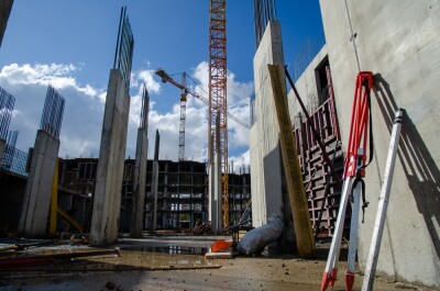
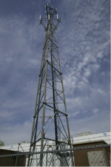
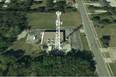
Here is an example project from which images were captured with a fully calibrated camera to satisfy rather challenging specifications.
The objectives were to
- analyze the orientation of the tilt and azimuth of the antennas at the top of the cell tower to ± 1º or better
- analyze the dimensions of the tower itself in three dimensions
- determine the absolute position of the tower relative to the national network
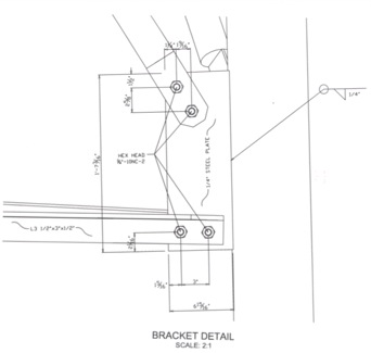
- create an as-built representation of structural details for the analysis of the tower components.
All analysis was to be derived from terrestrial close range photogrammetry.
Before proceeding to the field, the camera used was calibrated. GPS control around the tower was established. Next, the tower was photographed. The photographs processed and analyzed. The block was constructed and used to create the 3D model.
The calibration of the camera was performed using auto targets on portable sheets.
The calibration process refined the definitions of the fixed focal length, the actual relationship between the lens and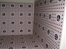 the picture plane, and the radial and tangential distortion parameters of the lens. The results were all stored in a camera calibration file for later use in the photographic analysis step.
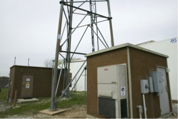
Ground control was established using both GPS and a total station. The stations, once placed, appeared in the subsequent photographs in order to aid in their coordination and scaling. In other words, the stations were used to establish the relative accuracy of the components of the work.
However, the stations were also necessary to establish the absolute accuracy of the tower’s position. “Absolute accuracy is stated with respect to adefined datum or reference system.” (ASPRS). In this case the reference system was the National Spatial Reference System established by the National Geodetic Survey.
Targets were placed on the tower and in its vicinity. The photography for the photogrammetric analysis was performed using a compact, handheld,digital camera from several camera stations.
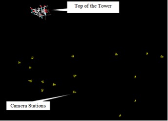
The analysis of accuracy availableto terrestrial close range photogrammetry has several components. Here is an important one: the size of the pixels relative to the length of the fixed focal length lens and the distance from the camera to the object.In this case, at the top of the tower using the 135mm (longest) lens the pixel size was 0.06 of an inch, using the 85mm (middle) lens the pixel was 0.2 of an inch, and using the 24mm (small) lens the size of the pixel was 0.07 of an inch. The best resolution expected to be available in this project was ½ of a pixel.
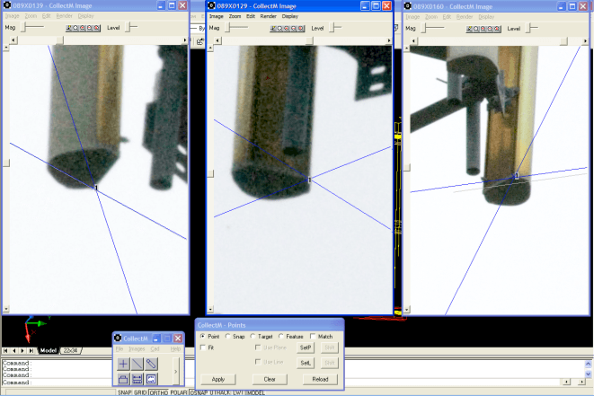
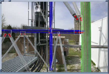
Next, the multiple photos of the tower were graphically connected into overlapping pairs, called stereomodels. These are the basic photogrammetric working unit. The orientation of the pairs was established by matching the relative orientation of tie pointsbetween images. These tie points include both features on the tower and the coordinated visible as targets in the photography. These common matched points in stereo-pairs were used to calculate the relationships of the photos themselves.
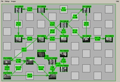
For photogrammetric analytics to proceed a block was formed.
Initially, all the photos in the block were transformed into an arbitrary image coordinate reference system. The origin of this coordinate system was based on the first photo inthe block. The orientation of each subsequent photo was determined by the tie points previously chosen.
Later, absolute orientation was established, the arbitrary image coordinate reference system was transformed into the real world (NAD83) using the coordinates established by survey. These values were made to harmonize with the image coordinates of the targets and tie points. Finally, the approximate locations and orientations of the photos were refined by simultaneously adjusting the image coordinate measurements, control point locations and camera exterior orientations to find the best overall solutions of the bundle. After a block was formed and oriented, it was refined for more accurate results using least squares solutions.
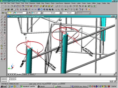
Once the photogrammetric database and block was completed, a 3D virtual model of the tower was available.