
At this past SPAR3D Conference I was fortunate enough to find our booth directly across the aisle from the booth for PointCab GmbH. During a break I was able to get a demo from CEO Dr. Richard Steffen and quickly added it to my list of things to research when I returned home. This past week I was finally able to put PointCab through its paces and I have to say that Dr. Steffen undersold it a bit.
I have a fairly well established scan-to-BIM workflow. My latest major overhaul occurred a bit less than two years ago when Jeff Williams and I began working together. We took the entire process back to zero and tested each phase. The results of that initiative are still the working model but we have edited something in the workflow about every three months to account for some new application or software update. It was with this mindset that I began evaluating PointCab, which bills itself as a universal application for analysis of all point clouds.
First–where PointCab fits in the scan-to-BIM workflow.
How I used PointCab
Dropping the entire point cloud of a structure into Revit can prove fairly useless. So, we have been slicing up the cloud into “model areas,” which could be anything from slices for a floor plan or reflective ceiling plan or an elevation view of a wall. The problem is scalability. When you get a large structure you can spend days prepping these files in Cyclone or ReCap. The idea I got from Dr. Steffen was that PointCab could automate this process.
He was correct that it gets you where you want to go, but the path is quite different than sticking with ReCap.
Essentially, PointCab (Ver. 3.5) accepts point cloud files (DP, e57, FARO, las, mps, ptg, and ptx, RIEGL, XYZ, & Z + F) and allows you to create cut planes in order to render layout views of the data within that cut plane. What’s more, this can be done with non-point cloud files (DAE, 3DS, IFS, STL, and ParaView files). PointCab doesn’t only create the layout images I previously mentioned, but it also takes the extra step of automatically creating the file that you want to use them in (DWG, DXF, Collada, DirectX, or 3DS).

A multi-level villa displayed in top view.
Layout & Section Tool
For the purposes of this review, I concentrated on the CAD DWG format, as my intention was to draw linework in CAD (using the orthogonal drawing tool) to use in Revit.
I started out in the PointCab Job Editor, where you can use the “Layout & Section” tool to control a bit of the DWG file’s properties, such as the background color, image format (PNG, JPG, TIFF, BMP, DDS, or WEBP), units, and projection type (3D, Planar, or Planar & Origin). You can also adjust the image resolution (1mm to 10m) and the color & reflectivity of the cloud, as well as options for scan radius and whether to include certain scan positions.
The standout differences are that the final rendered data is an image (or series of tiled images) and that you can stack these planes in a queue and process them all without having to sit and watch a task bar. The advantage of queueing is rather obvious and the images allow for users with less capable workstations to view high resolution data without rendering their files unworkable. If that was all that PointCab did, I would find it useful.
However, PointCab offers many other tools. In fact, I’m still working through some of the tutorials so it’s looking like this will be a two-part review. But first let’s cover a few more alterations to my current workflow.

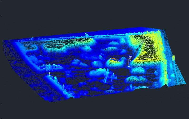
Data from a stone pit captured by UAV
Vectorizer Tool
Another feature is the “Vectorizer” tool. This tool is designed to take the images created by the Layout Tools and automatically create vector linework that can be edited and/or exported to CAD. Like most all automated modeling tools, it is far from perfect but there are times when it works very well. (As a caveat I have to state that I am working on an evaluation copy of the software that watermarks all of the images generated by the Layout tool. While this is understandable, the problem is that the Vectorizer tool cannot distinguish between the watermarks and the point cloud data. As a result, I can’t reliably report how long this would take if it wasn’t trying to make linework out of all of the watermarks.)
I’m still testing variations, such as differing image resolutions, collection devices and point cloud densities, but I’m pleased with the initial results. It will take some time to develop a best practices guide given all of the options.
However, additional downstream tools are also available in the Vectorizer module. For instance, the lines created by the Vectorizer tool are editable in PointCab. New vector points and lines can be created and existing lines can be intersected or joined at prescribed angles.
The last 2D tool in the Vectorizer menu is the Profiler tool. To use it, you simply use the “create line” command and make a new profile line. You can then duplicate that line however many time you like at whatever interval you choose. Lastly, select the Profile tool and define the accuracy of the profile line. The tool then produces 3D vector polylines of the profile aligned with each of the previously created 2D lines. It’s a very handy tool for road work, or to aid in the creation of simplified surface meshes.
Next week we’ll take a look at some of the other tools that are available in PointCab. Despite all of the coverage, I have yet to mention modules that can be used for point cloud registration, unwrapping cylindrical objects, deviation analysis, volumetric calculations, UCS editing, dimensioning, and meshing. If you are looking to get a jump on my efforts, an evaluation version can be downloaded from PointCab’s website.